Mac mini Wall Shelf: Agentic CAD, FEM, and Manufacturing Preparation
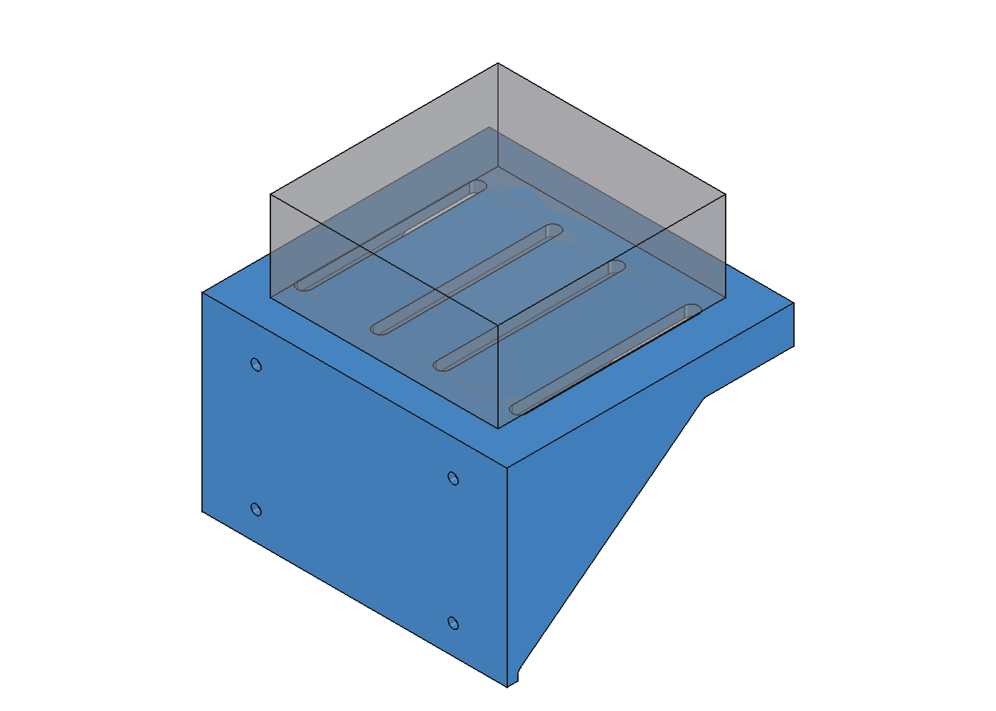
From Joe's requirements, Agentic AI produced the parametric CAD, four-case load analysis, convergence checks, support-free K1C toolpath, and visually inspected evidence package for a six-Mac-mini wall shelf.
The result is a digitally validated prototype and manufacturing package: a 170 x 160 x 106 mm watertight shelf, four checked load cases, a converged governing service result, and a support-free K1C slice. Physical print, installation, and load testing were not verified in the recovered evidence.
- Role
- Joe defined the objective, device count, printer constraint, and acceptance questions. Agentic AI verified the toolchain, generated the parametric model, checked geometry, ran and challenged the FEM, compared variants, prepared the K1C toolpath, rendered the evidence, and visually inspected the digital package.
- System boundary
- A scripted FreeCAD model produces one checked shelf solid and print-oriented STL. CalculiX solves spread and front-edge service and four-times overload cases; beam comparison, mesh refinement, a singularity demonstration, and a gusset-variant study challenge the result before OrcaSlicer produces the K1C manufacturing package.
- Primary constraint
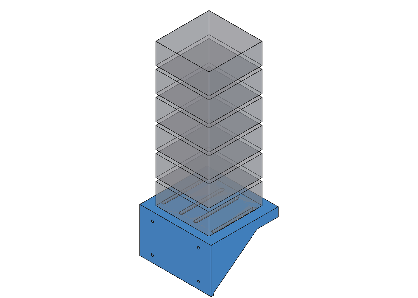
- Fit a 220 x 220 x 250 mm Creality K1C build volume as one support-free PLA body while holding six modeled Mac mini units plus stacking frames.
- Strongest evidence
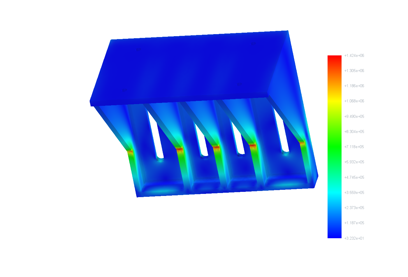
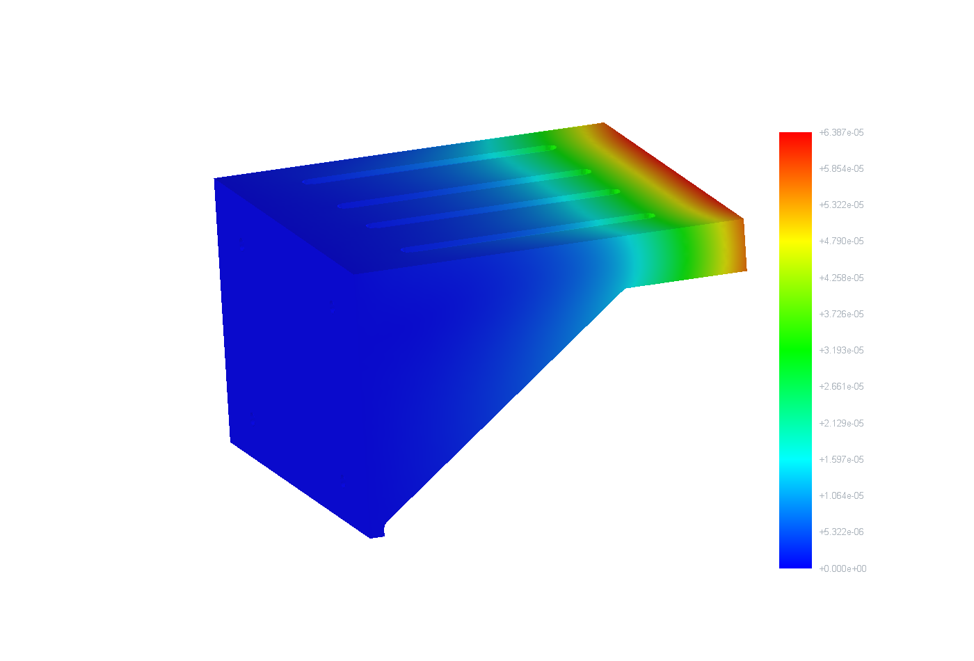
- The 48.8 N front-edge service case calculated 0.064 mm displacement and 1.42 MPa peak von Mises stress, a 3.5x margin against the selected 5 MPa PLA creep ceiling. The four-times front-edge case was transient analysis evidence, not a recommended service load.
The situation
Six Mac minis and their stacking frames needed a compact wall-mounted shelf that could be modeled as one printable body, fit the K1C envelope, preserve ventilation clearance, and expose its structural assumptions before consuming a day of printer time.
A shelf can look plausible in CAD while hiding a weak front edge, a stress singularity, unsupported print geometry, or an anchor assumption that the plastic model never tested. The useful outcome was therefore an auditable engineering chain, not a render and a PASS badge.
Constraints
- Fit a 220 x 220 x 250 mm Creality K1C build volume as one support-free PLA body while holding six modeled Mac mini units plus stacking frames.
- Use the governing 4.98 kg / 48.8 N front-edge service case and a sustained PLA creep comparison instead of presenting the more flattering centered-load or yield-only result.
- Separate solid, isotropic, rigid-wall FEM assumptions from the intended four-perimeter, 30% gyroid print and from untested drywall, anchor, heat, layer-adhesion, tipping, and long-term creep behavior.
- Publish authentic CAD and FEM renders without raw machine files, private paths, printer identifiers, transcripts, or unsupported physical-completion claims.
My responsibility
Joe defined the objective, device count, printer constraint, and acceptance questions. Agentic AI verified the toolchain, generated the parametric model, checked geometry, ran and challenged the FEM, compared variants, prepared the K1C toolpath, rendered the evidence, and visually inspected the digital package.
The system
A scripted FreeCAD model produces one checked shelf solid and print-oriented STL. CalculiX solves spread and front-edge service and four-times overload cases; beam comparison, mesh refinement, a singularity demonstration, and a gusset-variant study challenge the result before OrcaSlicer produces the K1C manufacturing package.
Architecture descriptionJoe's requirements flow through Agentic AI toolchain verification, parametric CAD, geometry checks, four FEM load cases, hand and mesh validation, variant selection, visual inspection, and K1C slicing, ending at a digital manufacturing package rather than a verified installation.
Agentic engineering loop / recovered digital toolchain
Human intent, agentic execution, bounded evidence
Joe defined the objective, constraints, and evidence boundary. Agentic AI performed the recovered digital toolchain across CAD, simulation, manufacturing preparation, and report cross-checking.
Recover the toolchain
Verify FreeCAD, CalculiX, meshing, rendering, and OrcaSlicer before modeling.Bound the problem
Set device, stack-frame, service-load, printer-envelope, and one-piece constraints.Generate parametric CAD
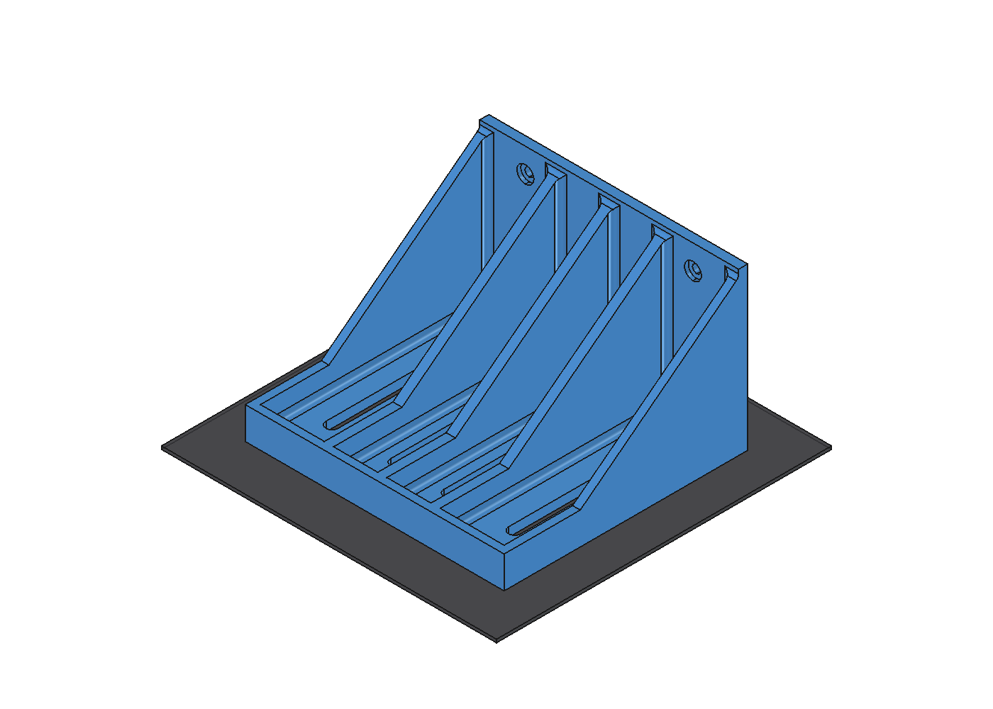
Build one FreeCAD solid with side walls, front apron, ventilation slots, and three gussets.Check manufacturing geometry
Prove validity, watertightness, manifold STL output, K1C fit, and support-free orientation.Solve four load cases
Compare spread and front-edge service loads plus their four-times transient overloads.Challenge the solver
Use beam theory, 6-to-4 mm mesh refinement, and a sharp-corner singularity demonstration.Compare variants
Measure the sustained-load cost of reducing the design from three gussets to one or none.Inspect and package
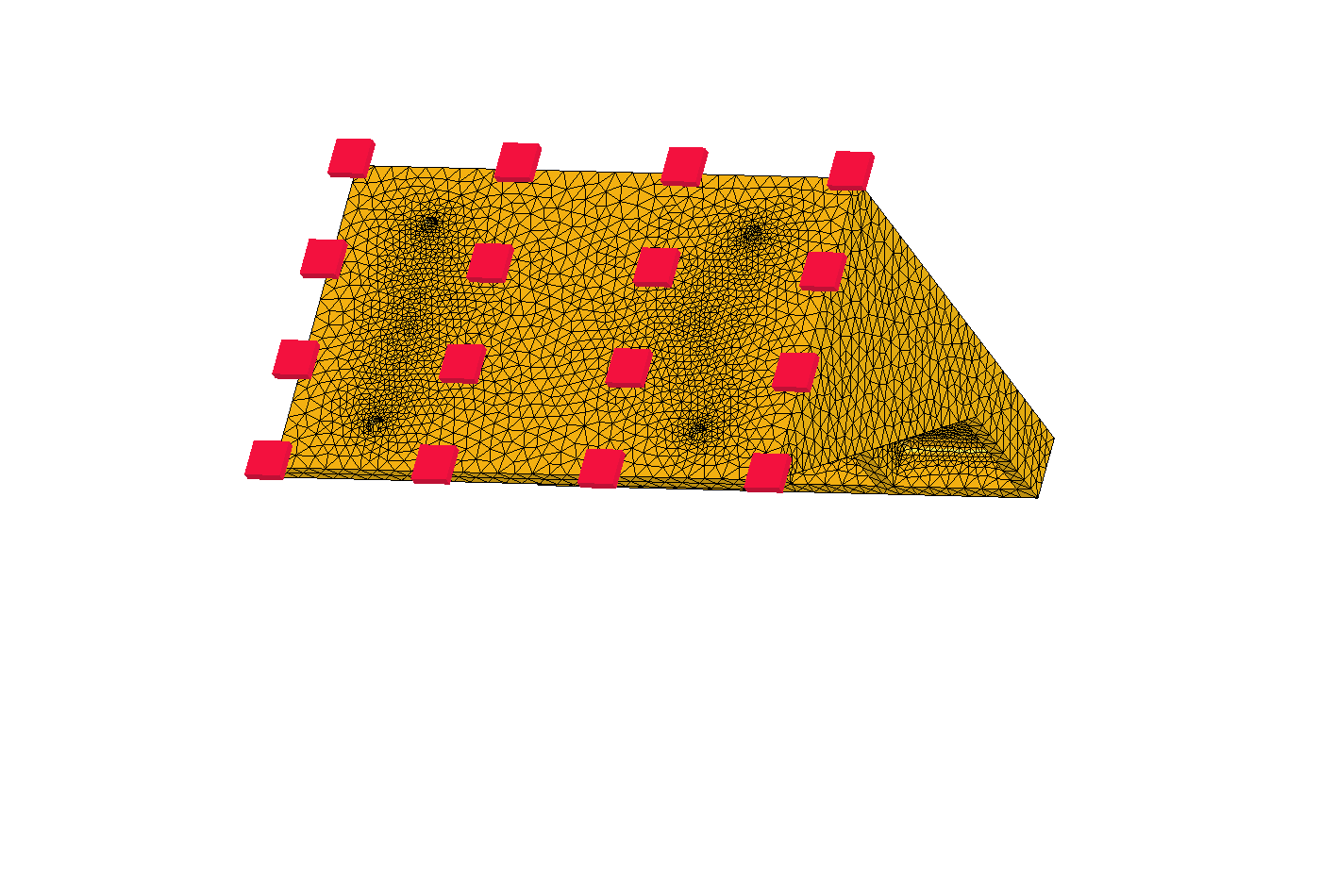
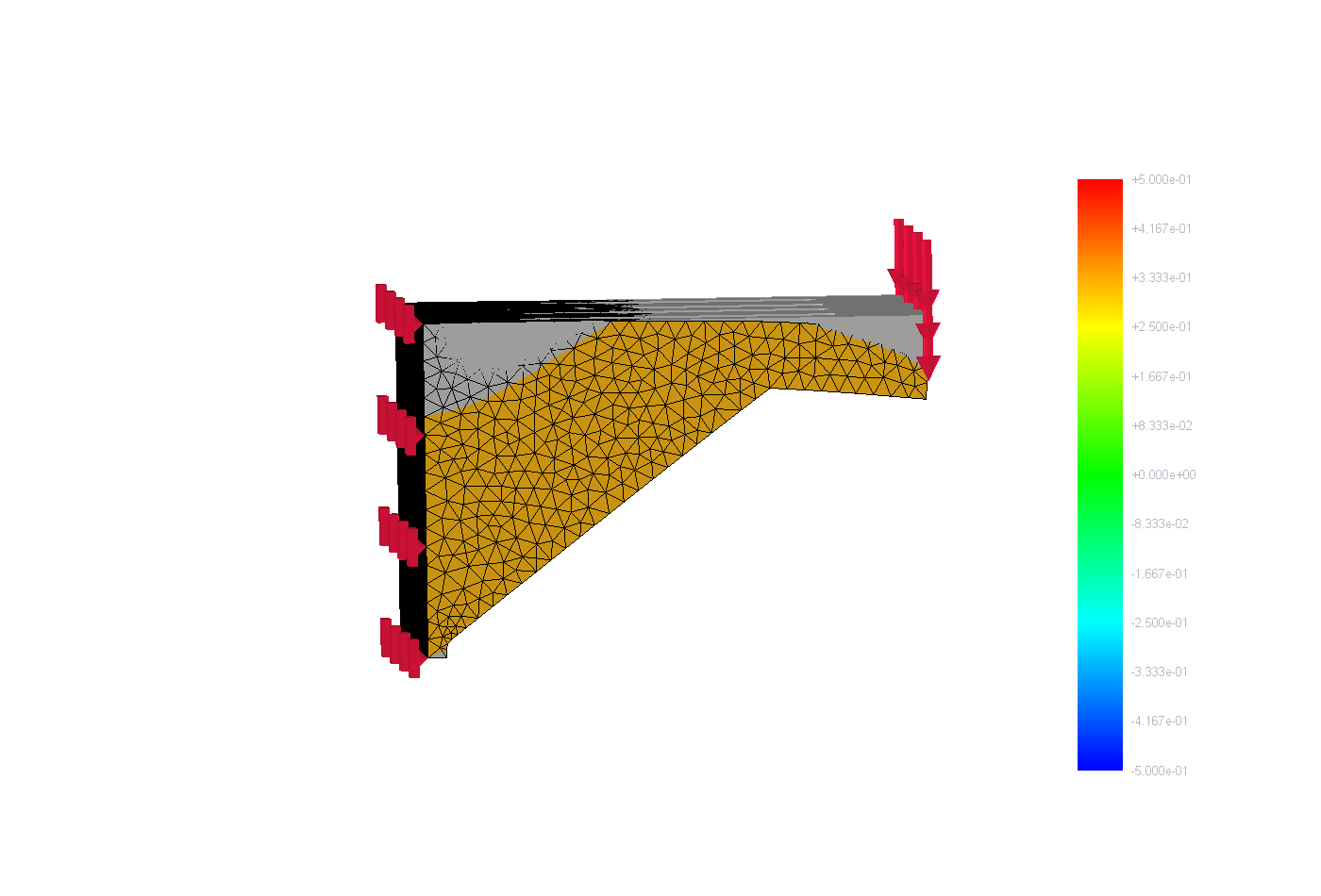
Render fit, constraints, mesh, stress, displacement, deformation, then slice and cross-check reports.
Model boundary
Inputs are not physical proof.
| Assumption | Status | Value or boundary |
|---|---|---|
| Shelf envelope | Measured artifact | 170 x 160 x 106 mm |
| Service load | Modeled input | 48.8 N / 4.98 kg |
| PLA material | Modeled input | E = 3000 MPa; Poisson ratio = 0.36 |
| Sustained ceiling | Engineering comparison | 5 MPa; not a certification limit |
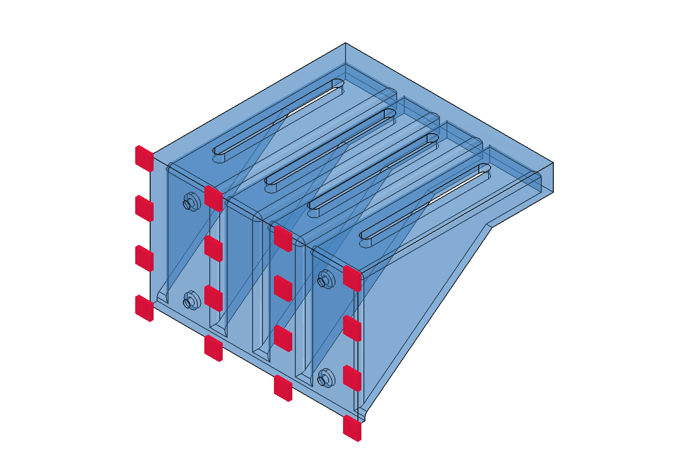
| Wall boundary | Modeled input | Back face held rigidly |
| Device contact | Modeled input | Distributed pressure, not four feet |
| Printed body | Unverified translation | Solid FEM versus four walls and 30% gyroid |
| Physical system | Not verified | Print, anchors, installation, heat, tipping, load test, and long-term creep |
Linear-static comparison
Front-edge loading governs.
| Case | Placement | Load | Deflection | Stress | Comparison |
|---|---|---|---|---|---|
| A | Service / spread | 48.8 N | 0.015 mm | 0.26 MPa | 19x to 5 MPa creep ceiling |
| C | Service / front edge | 48.8 N | 0.064 mm | 1.42 MPa | Governing sustained case; 3.5x |
| B | 4x / spread | 195 N | 0.060 mm | 1.03 MPa | 48x to 50 MPa yield |
| D | 4x / front edge | 195 N | 0.255 mm | 5.69 MPa | 9x to yield; not a service recommendation |
Critical decisions
01
Design for the front edge and sustained material behavior
- Choice
- Treat the 48.8 N front-edge service case and the selected 5 MPa PLA creep ceiling as the governing public comparison.
- Alternatives considered
- Lead with the centered spread-load case and compare only against short-term yield.
- Tradeoff
- The result is less dramatic than the early yield-margin headline, but it represents the load placement and long-duration behavior that matter more for this shelf.
02
Keep all three internal gussets
- Choice
- Retain the as-designed three-gusset body after the variant analysis produced a 3.5x creep margin.
- Alternatives considered
- Use one gusset at 1.7x creep margin.
- Use side walls alone at 1.2x creep margin.
- Tradeoff
- The stronger variant uses more PLA, but it preserves materially better sustained-load margin without adding supports or a second printed part.
03
Require scalar checks and visual checks
- Choice
- Pair build, solver, convergence, and slicer reports with explicit views of fit, print orientation, constraints, mesh, stress location, displacement, and exaggerated deformation.
- Alternatives considered
- Accept automated PASS summaries without inspecting the fields and geometry they summarize.
- Tradeoff
- The evidence package takes longer to generate, but visual inspection can reveal a reversed orientation, wrong boundary condition, poor mesh region, or misleading peak that a scalar result alone can hide.
Proof
Governing sustained-load analysisThe 48.8 N front-edge service case calculated 0.064 mm displacement and 1.42 MPa peak von Mises stress, a 3.5x margin against the selected 5 MPa PLA creep ceiling. The four-times front-edge case was transient analysis evidence, not a recommended service load.
- Evidence boundary
- Evidence covers the retained parametric CAD, one-piece geometry checks, four linear-static CalculiX cases, beam and mesh checks, a sharp-corner singularity demonstration, a three-variant gusset study, authentic rendered fields, and a support-free K1C toolpath.
- Known limits
- The FEM assumes isotropic PLA, a solid continuum, distributed pressure, and a rigid back face. It does not validate 30% infill behavior, layer anisotropy, wall compliance, anchor pull-out, thermal exposure, stack tipping, long-term creep, a completed print, installation, or physical load testing.
Engineering signal
Why this matters to engineering teams
The shelf demonstrates how Agentic AI can carry a bounded physical-product problem across CAD, simulation, manufacturing preparation, and evidence packaging while keeping human intent and unverified physical claims explicit.
End-to-end tool use
One workflow coordinated FreeCAD, CalculiX, geometry checks, variant analysis, rendering, and OrcaSlicer rather than stopping at generated code or prose.Adversarial validation
The analysis challenged its own attractive result with front-edge loading, a creep ceiling, beam comparison, mesh refinement, and a singularity demonstration.Visual verification
Fit, boundary conditions, mesh placement, stress location, displacement, and print orientation were inspected as engineering evidence.Honest handoff
The public result separates completed digital work from printing, installation, anchors, and long-term material behavior that still require physical proof.Captured evidence
Evidence gallery







Reflection
The result is a digitally validated prototype and manufacturing package: a 170 x 160 x 106 mm watertight shelf, four checked load cases, a converged governing service result, and a support-free K1C slice. Physical print, installation, and load testing were not verified in the recovered evidence.
- The governing case changed when the load moved from a favorable spread position to the front edge and the comparison changed from short-term yield to sustained PLA creep.
- Mesh convergence and a beam-theory comparison made the deflection result falsifiable, while the sharp-corner study showed why a stable-looking peak stress still needs interpretation.
- Visual inspection belongs inside an agentic engineering loop because an internally consistent report can still summarize the wrong geometry, load placement, or manufacturing orientation.